Building a VMware 2-node Cluster
Building a VMware 2-node Cluster on consumer hardware for my Homelab
A few months ago, I decided to build a vSphere 2-node cluster to play around with the rather new vSAN ESA architecture and high availability (HA) in general. The plan was to as well replace my current standalone ESXi (7) host with the new cluster.
The sense or nonsense of high availability in a home lab is certainly debatable, but in the end it still pays off, especially for internal network services like my virtualized pfSense firewall/router. Thanks to HA, I can now perform updates on one of the ESXi hosts without interrupting internal network traffic.
This blog post is primarily aimed at Homelab users and therefore deals mainly with the hardware. There are already numerous other articles on configuring vSphere 2-node clusters in general.
1 Hardware
A primary requirement when selecting the hardware was energy efficiency during idle or normal operation. In addition, the components should not be overly expensive and the CPU should offer a good balance between core count and single core clock rate (some of my specific workloads benefit enormously from high clock rates). Since vSAN ESA is particularly picky when it comes to using non-certified components, this factor also had to be taken into account.
In the end, I decided on the W680 consumer platform, which offers support for 14th generation Intel CPUs and up to 128 GiB DDR5 ECC RAM. The only disadvantage - which mostly all consumer platforms have - is the rather small number of PCIe lanes.
1.1 Case
The case of my choice is the rack mountable Inter-Tech 4U-40248, 4U. This has enough space for an ATX mainboard and ATX power supply and also offers the option of installing a tall CPU cooler and 2x 120mm fans. There are also numerous slots for HDDs/SSDs behind the fan mounts, two of which I use to mount the 2.5" vSAN SSDs.
1.2 Mainboard
The mainboard chosen was the ASUS Pro WS W680-Ace IPMI, which enables fully autonomous remote management via the IPMI card using the iKVM web interface. The board offers 3x M.2 SSD slots which are connected via PCIe 4.0 x4, as well as 2 PCIe 5.0 x16 slots, which unfortunately share the lanes. In this respect, either one of the slots can be operated with 16 lanes, or both slots with 8 lanes simultaneously. There are also 2 PCIe 3.0 x8 slots, both of which only provide 4 electrical lanes, and a single PCIe 3.0 x1 slot, which is reserved for the IPMI expansion card.
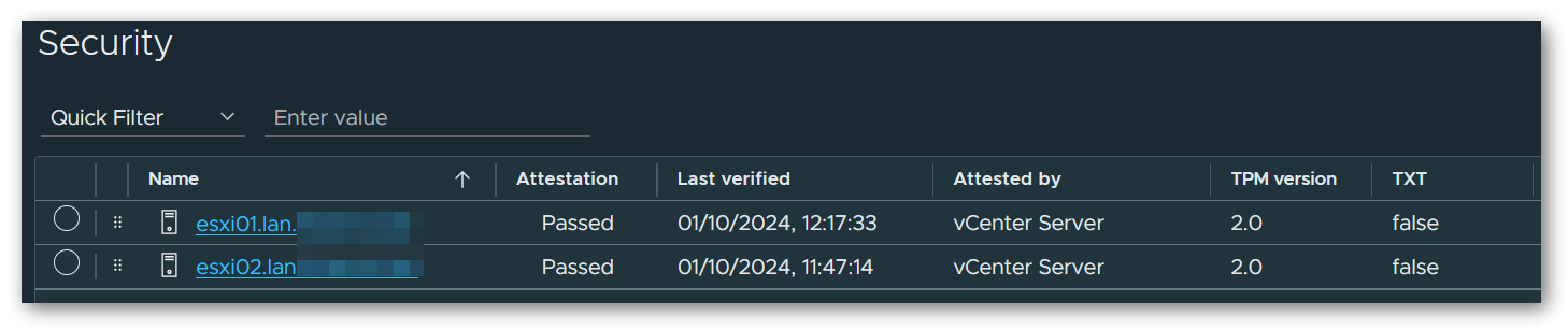
In order for the attestation of the ESXi hosts in vSphere to be successful later, a physical TPM 2.0 module is also required, which I purchased separately. ASUS itself offers the ASUS TPM-SPI Module, which is fully compatible with the mainboard and also supports the TIS/FIFO interface required by ESXi. Many TPM modules still work exclusively with the CRB interface, which cannot be used by ESXi.
TIS/FIFO interface is not activated correctly, a complete CMOS reset (via mainboard jumper) must first be performed after flashing the latest BIOS and the current ME firmware. After this, the TPM was immediately recognized and used correctly on both machines.Unfortunately, the in-band IPMI interface is not recognized correctly by ESXi and therefore no hardware sensors are displayed in the ESXi control panel or in the vSphere Client. The AST2600 chip is actually on the HCL, but there still seems to be a problem with the integration somewhere. However, as I can live with this, I have not yet carried out any further debugging.
1.3 CPU
The CPU used is the Intel Core i7-14700K, which contains 8 performance cores (base: 3.4GHz, boost: 5.6GHz) and 12 efficiency cores (base: 2.5GHz, boost: 4.3GHz).
1.4 RAM
For the RAM, I opted for 4 bars of Kingston Server Premier DIMM 32GB, CL46-45-45 @ 5600MHz, ECC (KSM56E46BD8KM-32HA) for a total capacity of 128 GiB. These modules are currently not on the QVL, but are working perfectly fine. If it is important to you to only use QVL listed RAM, you could also use the model KSM48E40BD8KM-32HM with CL40-39-39 @ 4800MHz as an alternative.
1.5 SAN Storage
As primary vSAN storage I use 2x Solidigm SSD D7-P5520 1.92TB, U.2 per host, which are connected to the onboard M.2 connectors via M.2 to U.2 adapter cable. These SSDs are qualified for vSAN ESA according to VMware HCL and are indeed correctly listed as “supported” in the vSphere control center.
The adapter cable used here is the Delock M.2 Key M to U.2 SFF-8639 NVMe Adapter.
1.6 OS Storage
Since the mainboard has a total of 3 M.2 ports and I only use 2 of them for the vSAN SSDs, a Samsung SSD 980 PRO 500GB, M.2 is used as storage for the operating system for the sake of simplicity. Alternatively, you could also use a SATA DOM here, but in my case at least, these were far less available and also a little more expensive than the simple Samsung SSD.
1.7 NICs
In addition to the two onboard 2.5G ethernet ports, I have installed a NVIDIA Mellanox ConnectX-5 EN 25G NIC, which has 2 ports that can be operated in 25G mode via SFP28 module, or in 10G mode via SFP+ module. This card requires a connection via PCIe 3.0 x8, which means that we have to use one of the PCIe 5.0 slots on the mainboard for full bandwidth (both PCIe 3.0 x8 slots on the mainboard are only connected with x4 electrical lanes).
1.8 Power Supply
The power supply is a Seasonic Prime PX-750 750W ATX 2.4, which has a very high efficiency thanks to “Platinum” certification and offers more than sufficient power at 750W.
1.9 Cooler
As CPU cooler I use the Alpenföhn Brocken 4, which, when installed, is flush with the lid of the case down to the last millimeter. There are mounting slots on the heat sink for up to 2x 120mm fans, on which I have installed two Arctic P12 Max fans instead of the included ones. More about these in the next section.
1.10 FANs
In addition to the two fans on the CPU cooler, another 2x Arctic P8 Max and 2x Arctic P12 Max PWM fans are used, for which I have replaced the pre-assembled models in the case. These fans are very quiet at low speeds, but can also generate a lot of static pressure if necessary. If desired, a 0-RPM mode is also available.
2 Configuration
For initial configuration of the cluster, I followed the blog post Configure 2-node vSAN Cluster (ESA) by “Seyed Yahya Zahedi Fard”.
Some adjustments were necessary, which I describe in the following sections.
2.1 Distributed Switches
In the linked article, the author uses 2 dedicated NIC ports with failover for each of the networks Management, Production, vMotion and vSAN. Since the network card I chose only has 2 ports in total, I adjusted the network configuration as follows:
For Management and Production, I created a distributed switch that uses port 1 as an uplink and is connected directly to a physical switch via this port. Both the management network and the individual segments of my production network are separated by VLANs.
Management network is called Datacenter in my configuration.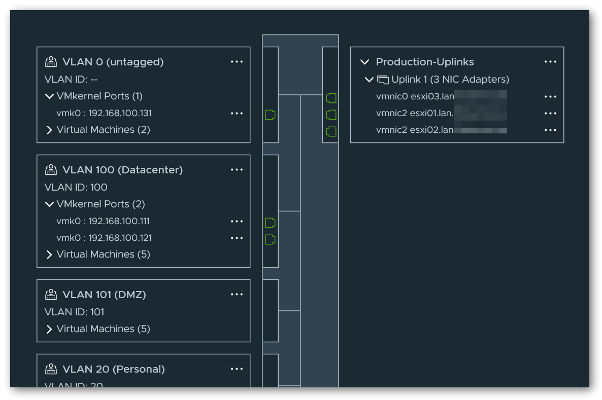
For vMotion and vSAN, I have created another distributed switch that uses port 2 as an uplink and connected it to the other node via a DAC cable. Again, I have isolated the networks using a VLAN tag on the corresponding port groups.
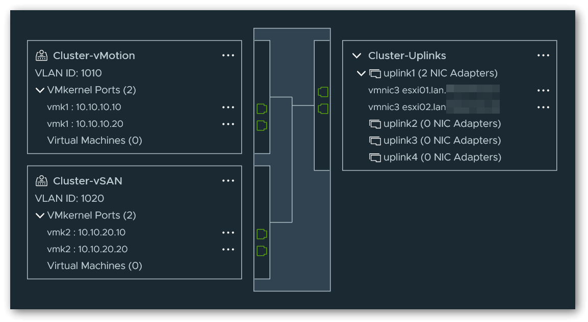
vMotion/vSAN switch so that the pre-configured switch is later correctly presented for selection in the cluster setup wizard. However, it is sufficient if only one of the uplinks is assigned a NIC port. Once the cluster has been completely set up, the additional virtual uplink can optionally be removed without any problems.2.2 Witness Traffic Separation
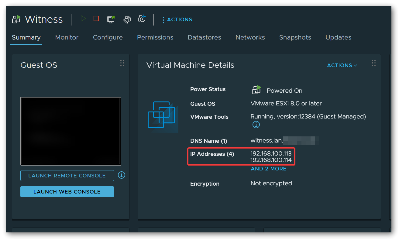
A small adjustment must also be made when configuring the Witness Appliance. Due to the direct connection of the two nodes, the vSAN network is locally isolated and no data traffic can flow from/to the vSAN Witness Appliance. The “Witness Traffic Separation (WTS)” concept can be used to solve this problem. For this purpose, I have set both the Management Network and the Secondary Network (usually vSAN) to the management network port group of the 1st distributed switch when deploying the Witness Appliance.
In the VMkernel adapters of both nodes, vSAN Witness must now also be activated under Enabled services of the management VMKernel network adapter (usually vmk0).
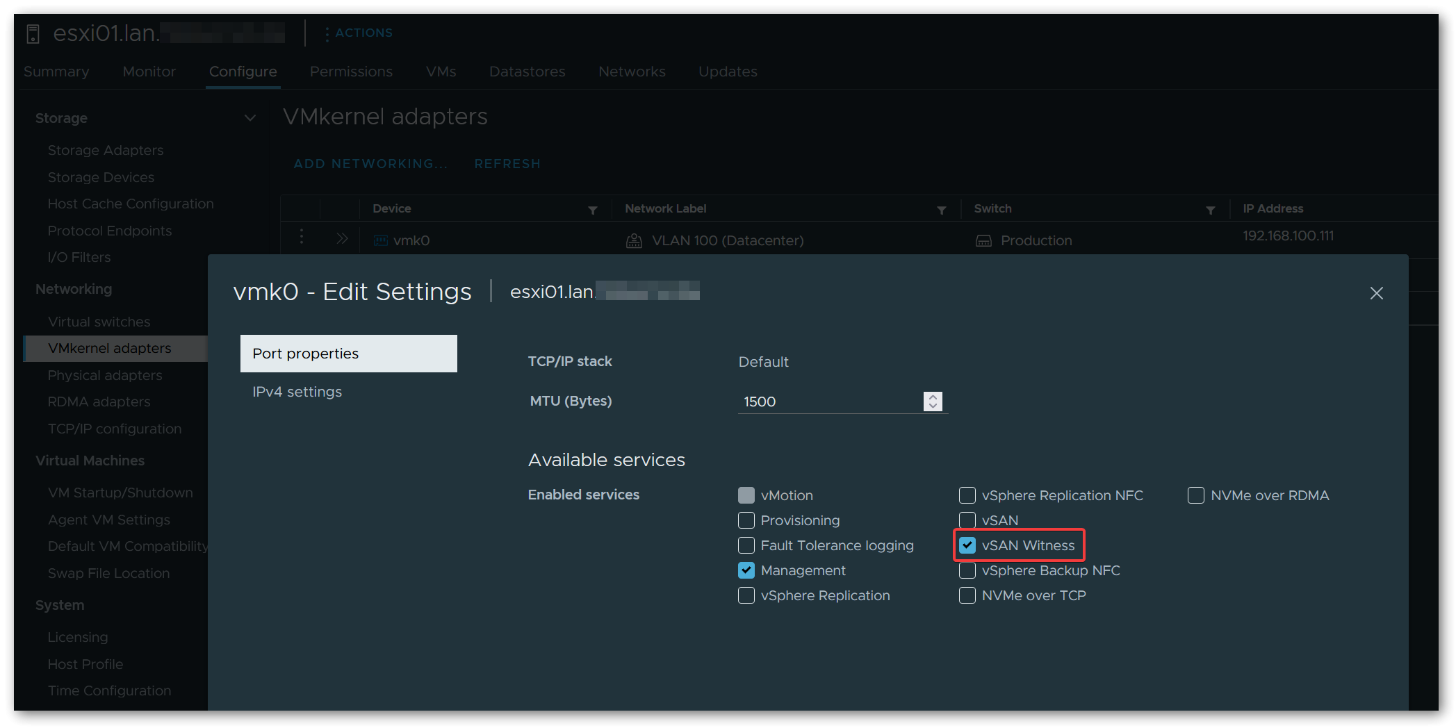
This configuration allows regular vSAN traffic to flow directly between the nodes via the 2nd distributed switch, while vSAN Witness traffic uses the 1st distributed switch and the management network connected to it.
Instead of using the management network, an additional network segment/VLAN and an additional VMKernel adapter could have been used for this, but I decided not to do this for the sake of simplicity.